Introduction
Welcome, and thank you for your interest in building a SFWEM Portable Access Node (PAN). Please note:
• This is a living document, and subject to improvement.
• This is not an endorsement of specific brands or resellers. It is provided for your convenience.
• If you have your own substitutions, tripod, power supply, what ever your imagination brings, please feel free to customize. These components are known to work allowing easy support through standardization.
Add a Camera to your PAN
Add a Cisco SPA 525G to your PAN
Bill of Materials
| Component | Description | PICT | |||
|---|---|---|---|---|---|
| Base | WEM Radio | Ubiquiti Nanostation NSM5 | A | BUY | BUY |
| Base | Battery | U12-8F | B | BUY | BUY |
| Base | Tripod | Neewer Pro 9’ AluStudio Light Stands | - | BUY | BUY |
| Base | Sandbags | Neewer 8 Pack Dual Handle Sandbag | - | BUY | BUY |
| Base | Wi-Fi Radio | Ubiquiti AirGATEWAY PRO | C | BUY | BUY |
| Base | Voltage Converter | DC 12V Step Up to 24V 72W | D | BUY | BUY |
| Base | Case | 9X6X3 Weatherproof Enclosure | E | BUY | BUY |
| Base | POE Injector | POE Injector | F | BUY | BUY |
| Base | Ethernet A | 6” Ethernet Cable | G | BUY | BUY |
| Base | Ethernet B | 14’ Ethernet Cable | H | BUY | BUY |
| Base | Terminal Conn. | Crimp on female connector | I | BUY | BUY |
| Base | 3M HB Tape | High bond, two sided tape | - | BUY | BUY |
| Base | Charger | NOCO GENIUS1, 1-Amp Fully-Automatic Smart Charger | - | BUY | BUY |
| Option | Quick Connect | NOCO GC015 X-Connect M10 Eyelet Battery Indicator Accessory | J | BUY | BUY |
| Option | Quick Connect | Custom Powerpole made to order | - | BUY | BUY |
Items above listed as "Option" are optional components to add features to the base model of the PAN.
PICT: Reference number for PICT below in "Assembly."
Additional Tools
PC w/ Ethernet
Software/Firmware
Screwdriver
Utility knife
Velcro+Screw
Zip ties
Rubbing Alcohol
Assembly
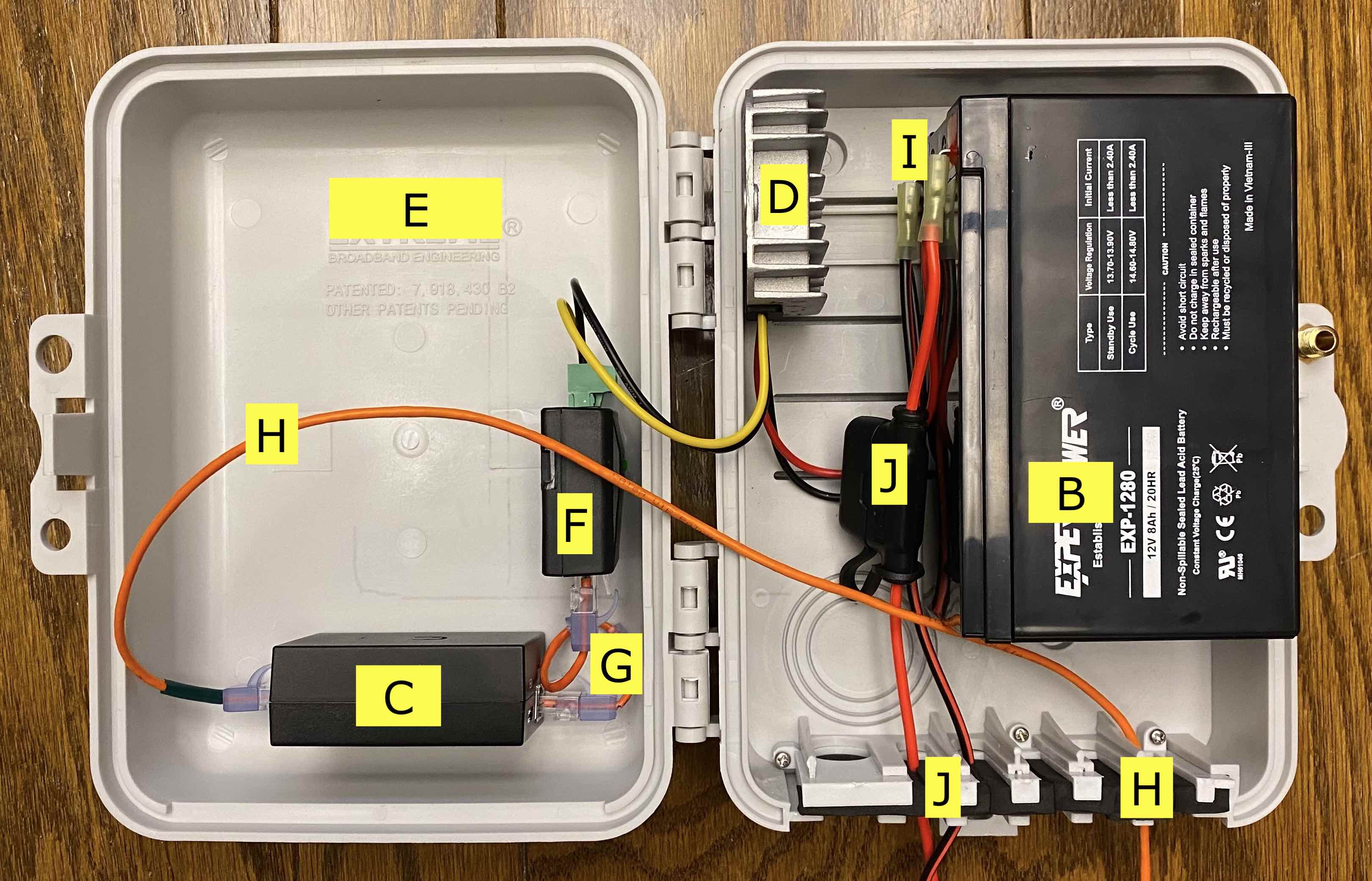
Weather Resistant PAN case, open, showing internals. Please use letters to reference item from Bill of Materials above.
Voltage Converter Install
- If your voltage converter has it's pinout described on its smooth, bottom surface, use a Sharpie to transcribe the pinout to the side of the converter where the wires exit the rectifier. See FIG 01.
- Apply some rubbing alcohol to a ball of cotton, and wipe the bottom of the converter and the area of the case where the converter will be installed.
- Apply a piece of two sided foam tape to back of converter. See FIG 02.
- Remove liner from two sided tape, then affix converter to case as illustrated. See FIG 03.
POE Injector Install
- With a utility knife, cutting away from yourself, remove the eyelets from the POE Injector. See FIG 04.
- Apply some rubbing alcohol to a ball of cotton, and wipe the bottom of the rectifier and the area of the case where the rectifier will be installed.
- Apply a piece of two sided foam tape to back of POE Injector. See FIG 05.
- Remove liner from two sided tape, then affix POE Injector to case as illustrated. See FIG 06.
- Connect the 24v wires from the rectifier into the appropriate screw down connector on the POE Injector.
PRO TIP: When connecting the feed wires, insert the wires with a little twist to encourage a slight curl to the wires.
AirGATEWAY Install
- Remove rubber outer protective case. See FIG 07.
- Apply some rubbing alcohol to a ball of cotton, and wipe the bottom of the rectifier and the area of the case where the rectifier will be installed.
- Review orientation and placement of AirGATEWAY, we will install this component with the POE IN very close to the POE Injector using the short ethernet cable.
- Apply a piece of two sided foam tape to back of rectifier. See FIG 08.
- Remove liner from two sided tape, then affix rectifier to case as illustrated. See FIG 03.
- Modify the short ethernet cable by carefully cutting the articulated stress relief plastic taking extra care to not damage the cable. On the cable used for this example, it was two small cuts. We did not make additional cuts to remove the unneeded material, you can if you want.
Flashing and AirGateway Setup
M5 Flash with ARDEN Firmware
Read the official Arden instructions here: https://arednmesh.readthedocs.io/en/latest/arednGettingStarted/installing_firmware.html
AirGATEWAY PRO Set-up
These instructions were written using AirGateway Pro Firmware 1.1.10. Firmware 1.1.11 and newer are not compatible with this configuration, please downgrade your firmware.
1. To connect to the AirGATEWAY PRO's web interface, follow instructions included in its package or the manufacturers web site. (192.168.1.1 Username: ubnt PW: ubnt) If this is your first time logging into this AirGATEWAY PRO, you will need to select a country, select a language, plus check the box to agree to their license agreement, finally press login. Be advised, you may need to configure your computer to "static IP" mode and assign it an ip address in range with the AirGATEWAY such as 192.168.1.100.

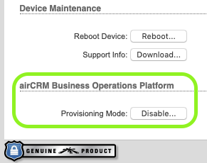
2. Key Step: Disable the "airCRM Business Operations Platform Provisioning Mode"
A: Click on the System Tab.
B: In the lower left corner of the web control panel, find the "Provisioning Mode" setting, then click the "Disable..." button.
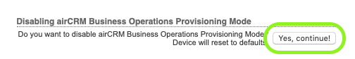
C: A confirmation pop-up box will appear, press the "Yes, confirm" button to confirm the Provisioning Mode change.
4. Wait about one min for the AirGATEWAY to reboot.
5. Join a new wi-fi network on your computer, look for SSID "www.ubnt.com" and join.
6. Connect to the AirGATEWAY web admin interface again at 192.168.1.1 using Username: ubnt PW: ubnt
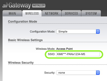
7. Navigate to the tab: Wireless
A: Change the SSID, suggestion: CALL-PANxPPPP-M5; where CALL is your call sign, PAN because this is a portable access note, the PPPP will be the phone extension to be hosted by the PAN, followed by M5 which is the device type identifier a Rocket M5 in this example)
B: Add a password if desired, you may consider not adding one to make joining the network when deployed easier.
C: Click the "Change" button to save the changes.
D: Click the "Apply" button in the blue info bar at the top of the screen.
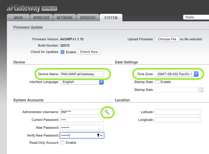
8. Go to the tab: System
A. Update the Device Name.
B. Update the Time zone.
C. In the System Accounts section, click the key icon to change the default administrator username field.
D. Change the Administrator Username. We suggest your call sign.
E. Enter the Current Password: ubnt
F. Enter a new password in the two provided fields.
G: Click the "Change" button to save the changes.
H: Click the "Apply" button in the blue info bar at the top of the screen.
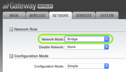
9. Navigate to the tab: Network
A: Change the Network Mode to "Bridge"
B: Click the "Change" button to save the changes.
C: Click the "Apply" button in the blue info bar at the top of the screen.
SFWEM is a volunteer-led project.
v2.0 Last Updated: 08-28-2020